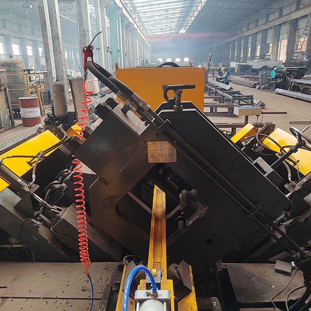
Drilling structural angle steel presents unique challenges—specifically uneven leg thicknesses, inherent material stresses, and vibration risks that destroy tooling. Fabricators often face the frustrating reality of shattered bits and ruined materials. Incorrect drill bit geometry or mismatched spindle settings result in rapid tool wear, work hardening, and out-of-tolerance holes. This creates severe production bottlenecks down the line. You simply cannot rely on guesswork when dealing with high-yield structural components. Achieving consistent, high-volume hole quality requires matching the right cutting tools and RPM/feed parameters with the structural rigidity of purpose-built equipment. In this guide, we break down optimal drill bit selections, precise spindle settings, and the machine requirements necessary to scale your structural fabrication efficiently.
Key Takeaways
Optimal Geometry: 135-degree split-point drill bits are standard for angle steel to prevent "walking" on uneven surfaces.
Material Matching: High-Speed Steel with Cobalt (HSS-Co) offers flexibility, while Solid Carbide requires extreme machine rigidity to prevent shattering.
Parameter Baseline: Spindle speeds and feeds must be calculated based on Surface Feet per Minute (SFM), adjusting downward for high-yield structural steel.
System Integration: Maximizing tool life and throughput at scale requires transitioning from manual setups to a fully automated CNC Angle Drilling Marking Line.
The Mechanical Challenges of Drilling Angle Steel
Inefficient drilling creates major bottlenecks for downstream assembly processes. This problem frequently plagues structural fabrication shops and transmission tower manufacturing facilities. When structural holes fall out of tolerance, workers waste hours reaming and aligning parts on the job site. You must address the root mechanical causes at the machine level to maintain profitable production flow.
The characteristic L-shape of angle steel makes it highly susceptible to micro-vibrations. Standard flat bar rests securely on a machine bed, but angle iron features an offset center of gravity. If you fail to clamp it securely, the unsupported leg acts like a tuning fork during the drilling process. You must deploy high-pressure hydraulic systems to lock the material down. Without immense clamping force, lateral movement occurs. This invisible shifting snaps brittle cutting edges almost instantly.
Work hardening presents another hidden danger during fabrication. As the cutting tool reaches the bottom of the cut, it experiences a phase called breakthrough. The material here is thin and flexible. If the feed rate hesitates or drops during this split second, the tool stops shearing and starts rubbing. This dwell time generates enormous heat, causing mild and high-yield steels to harden rapidly at the exit point. Once the steel hardens, it will severely damage or completely destroy the drill bit on the very next revolution.
Evaluating Drill Bit Types and Point Angles
Selecting the correct point angle dictates how your tool interacts on an uneven structural surface. You must choose carefully between standard geometries and split-point configurations to achieve clean, accurate holes.
118° vs. 135° Split Point
Standard 118-degree bits work adequately for general, softer materials. However, they tend to wander aggressively when cutting into hot-rolled angle steel. This wandering ruins hole accuracy before the cut even truly begins.
Conversely, 135-degree split-point bits serve as the undisputed industry standard for structural applications. They require slightly more thrust to penetrate the initial metal surface. In return, they offer superior self-centering capabilities. This geometry bites into the uneven mill scale immediately, ensuring faster penetration rates and preventing lateral drift.
Material Selection (HSS-Co vs. Carbide)
Tooling material selection depends entirely on your specific machinery capabilities. You generally choose between two primary categories.
HSS-Co (Cobalt): This alloy remains the best choice for older or less rigid machines. Cobalt bits handle heat better than standard high-speed steel. Crucially, they tolerate slight lateral movement safely without snapping, making them forgiving in sub-optimal setups.
Solid Carbide / Replaceable Tip: These advanced tools deliver tremendous speed advantages. They typically cut three to five times faster than cobalt. However, they mandate absolute machine rigidity and continuous flood coolant. You will only find them viable on heavy-duty, modern CNC machinery. Any vibration will shatter the carbide insert instantly.
Coolant Delivery
Managing heat generation dictates total tool longevity. Internal coolant hole oil drill bits, frequently referred to as through-spindle coolant tools, are critical for continuous deep-hole drilling. Standard flood coolant often fails to reach the cutting edge inside a deep hole. Through-spindle designs pump coolant directly down the center of the tool. This flushes chips out of the flutes forcefully while preventing fatal thermal shock to the cutting edges.
Drill Bit Material Comparison Chart
Tool Material
Machine Rigidity Requirement
Relative Cutting Speed
Vibration Tolerance
Best Application
HSS (Standard)
Low
Baseline (1x)
High
Manual drill presses, mild steel
HSS-Co (Cobalt)
Moderate
Fast (1.5x)
Moderate
Older machinery, tougher steel grades
Solid Carbide
Extreme
Ultra-Fast (3x-5x)
Very Low
Modern CNC centers, high-volume production
Establishing Baseline Spindle RPM and Feed Rates
Before touching a dial, you must run a strict assumption check. Cutting parameters vary wildly based on your specific material grade. Processing standard A36 mild steel differs vastly from plunging through A572 Grade 50 high-yield structural steel. Your machine condition also severely impacts the final optimal settings.
Calculating the proper RPM requires a strict focus on Surface Feet per Minute (SFM). SFM measures the speed at which the outer edge of the tool passes over the material. For mild steel using HSS tooling, you should target an SFM between 70 and 100. If you switch to carbide tooling on mild steel, you can push speeds dramatically higher. In rigid setups, target 200 to 300+ SFM.
Feed rates control the chip thickness and dictate how aggressively the tool advances. We measure this in Inches Per Revolution (IPR). Maintain an aggressive, consistent feed rate ranging from 0.004” to 0.012” IPR, depending on the tool diameter. You must ensure the tool actually shears the metal. If the feed rate is too light, the bit rubs against the steel. Rubbing generates extreme friction, accelerating wear and ruining the temper of the cutting edge.
Finally, you must program a reliable breakthrough protocol. As the bit exits the bottom of the angle iron leg, it loses continuous material resistance. The flutes can easily grab the jagged exit material. Reduce your feed rate by 30 to 50 percent just before breaking through. This simple adjustment prevents grabbing, eliminates spindle stalling, and drastically reduces catastrophic tool breakage.
Why Tool Life Depends on the Right Angle Drilling Machine
Consumables only take your production so far. Even premium carbide bits will fail prematurely if your spindle lacks continuous torque. Spindle stall under heavy load destroys edges immediately. Similarly, if the machine frame lacks sufficient mass, natural vibration will kill your tooling. You cannot compensate for a weak machine foundation by buying more expensive drill bits.
You must evaluate structural equipment using rigidity as a primary success criterion. Any serious assessment of drilling capability must closely examine the cast or welded frame weight. Heavy frames absorb resonance effectively. Additionally, evaluate the strength of the hydraulic clamping mechanisms. Choosing a specialized angle drilling machine solves these mechanical shortcomings directly by gripping the specific L-shape profile securely across multiple axes.
Modern automated controllers eliminate operator guesswork entirely. They strictly enforce programmed RPMs and feed rates. This automation actively prevents the manual "easing up" habit. In manual setups, operators often slow down the feed handle instinctively when they hear the machine working hard. This hesitation causes immediate work hardening at the bottom of the hole. Automated controllers push through the cut consistently, preserving the tool edge and ensuring repeatable hole tolerances.
Scaling Production with a CNC Angle Drilling Marking Line
Transitioning from standalone drill presses or manual ironworkers significantly boosts overall shop output. The most effective upgrade path involves installing an integrated CNC Angle Drilling Marking Line. This solution category shifts fabrication from a segmented, labor-intensive process into a continuous, data-driven workflow.
When evaluating these automated systems, you should examine three specific dimensions.
Spindle Power & Automation: Look for advanced multi-spindle configurations. A multi-axis CNC angle drilling line drills both legs of the profile simultaneously. It accomplishes this without requiring operators to flip or reposition heavy stock, drastically reducing handling times.
Integrated Processing: Combining the drilling unit with a reliable steel tower marking machine module is crucial. It allows seamless, inline part identification via stamping or scribing. This integration proves vital for organizing complex field assemblies like telecom towers and high-voltage transmission structures.
Throughput vs. Footprint: Evaluate the actual floorspace required for the complete line, including material in-feed and out-feed conveyors. Weigh this footprint against the massive labor hours saved by fully automated feeding, hydraulic clamping, marking, and drilling. You typically reclaim valuable shop space by eliminating scattered manual workstations.
We must also acknowledge the implementation risks associated with scaling. Upgrading to advanced machinery requires upfront preparation. You must ensure your operators receive adequate training on CNC conversational programming interfaces. Furthermore, your facility must possess sufficient chip-conveyor systems and proper coolant-recycling infrastructure. High-speed drilling generates massive amounts of steel chips and requires efficient coolant filtering to run continuously.
Conclusion
When evaluating structural steel processing equipment, you should apply a strict shortlisting logic. Always prioritize machines supporting through-tool coolant systems. Insist on programmable spindle feeds capable of handling rigid carbide tooling safely. Finally, demand robust hydraulic clamping to eliminate the micro-vibrations inherent in L-shaped profiles.
Take immediate action by auditing your current operations. Monitor your weekly tool consumption and measure your average hole cycle times. If drill bit failure or slow manual layout processes currently cap your structural output, request detailed time-studies from equipment manufacturers based explicitly on your specific structural angle profiles.
FAQ
Q: Can I use solid carbide drill bits on a manual angle drilling machine?
A: It is highly discouraged. Manual feeds and lighter machine frames allow micro-vibrations, which will quickly shatter brittle carbide bits.
Q: How does a CNC angle drilling line handle different steel grades?
A: CNC controllers store material-specific tool libraries. Operators simply select the material (e.g., A36 vs. Grade 50), and the machine automatically adjusts to the optimal spindle RPM and feed rate.
Q: Do I need a separate steel tower marking machine if I buy a CNC drilling line?
A: No. High-quality CNC angle lines feature integrated hydraulic or pneumatic marking units that stamp part numbers and layout marks immediately before or after the drilling sequence, ensuring absolute accuracy.