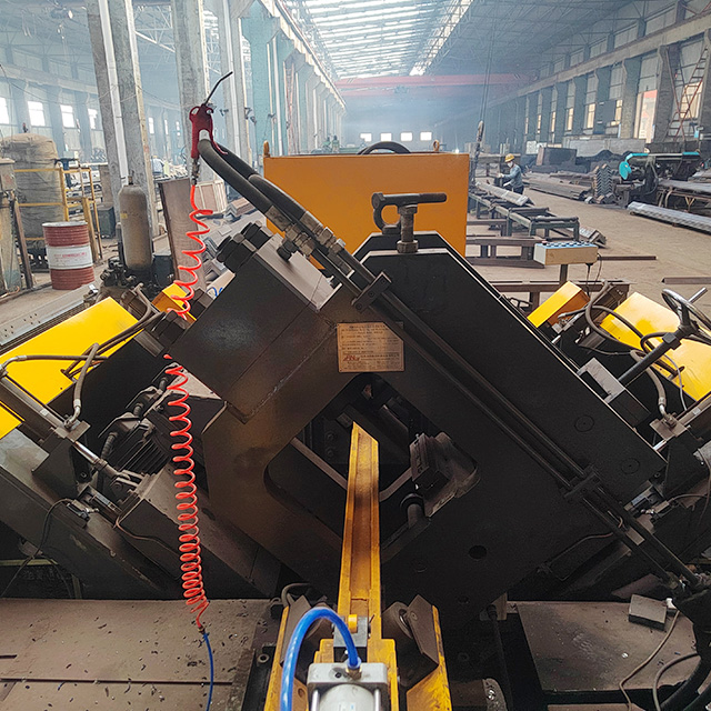
Hole position errors in structural steel cost fabrication shops thousands in lost time and scrapped materials daily. When holes do not align, downstream assembly stops completely. Forced rework creates expensive bottlenecks. Manual layout and conventional 3-axis workarounds leave far too much room for human error. They frequently introduce positional drift, causing compromised structural integrity across heavy manufacturing projects. Relying on tape measures or makeshift jigs often leads to unpredictable scrap rates and missed deadlines.
You need better control over your hole-making processes. This article evaluates how purpose-built CNC angle processing equipment mitigates drift and standardizes tight tolerances. We will explore how automated solutions eliminate variables and drive reliable, precise production outcomes. By understanding the mechanics of these systems, you can confidently eliminate the assembly line bottlenecks hurting your margins. You will learn actionable evaluation criteria to upgrade your structural steel fabrication workflow.
Key Takeaways
Automated Precision: CNC angle drilling eliminates manual layout variables, drastically reducing human error in hole placement.
Integrated Marking: A CNC Angle Drilling Marking Line combines hole making with part identification, streamlining downstream assembly.
Rigidity & Clamping: Purpose-built equipment utilizes specialized hydraulic clamping to prevent material shift and tool deflection during heavy drilling.
Software Alignment: Direct CAM-to-machine data transfer prevents translation errors common in manual programming.
Evaluation Criteria: ROI depends on analyzing clamping mechanisms, spindle rigidity, tool wear compensation, and software compatibility.
The Financial and Structural Cost of Hole Position Errors
Out-of-tolerance holes create a massive assembly bottleneck. When structural components arrive at a job site with misaligned holes, erection crews face severe delays. Workers must force connections or perform on-site reaming. Field modifications waste expensive labor hours. They also increase the risk of scrapped material. If a steel angle piece requires excessive reaming, it often fails quality inspections. You must then fabricate a replacement part from scratch. This process derails project timelines entirely.
Positional drift stems from several common failure points found in conventional processing methods. Manual measurement drift remains the primary culprit. Human operators cannot maintain sub-millimeter precision consistently over an eight-hour shift. Tool deflection also causes significant drift. When using inadequate fixturing, the material shifts slightly upon drill contact. Furthermore, thermal expansion during heavy cutting can warp the workpiece. Makeshift jigs on standard milling machines simply cannot handle long steel angles securely.
Inaccurate hole placement introduces severe compliance and safety risks. Load-bearing structures demand absolute precision. Frameworks like transmission towers rely on exact geometric alignment to distribute weight safely. The American Institute of Steel Construction (AISC) and ISO standards mandate strict positional tolerances. Non-compliant connections weaken structural integrity. They create localized stress concentrations. Eventually, these weak points can cause catastrophic structural failures. Fabricators must prioritize standardized, verifiable accuracy to avoid these liabilities.
Mechanics of Accuracy: How a CNC Angle Drilling Marking Line Eliminates Variables
Automated material indexing transforms long-stock fabrication. Servo-driven feeding carriages grip the steel securely. They advance the material along the X-axis with incredible precision. These systems ensure absolute positioning accuracy across extremely long lengths of angle steel. You no longer rely on manual tape measurements. The machine's encoders read exact coordinates continuously. This closed-loop feedback eliminates cumulative length errors along a 12-meter structural beam.
Simultaneous processing provides another major advantage. Dedicated equipment often features multi-spindle setups. These spindles attack both flanges of the angle iron at the same time. You process the entire cross-section without unclamping or repositioning the material. Every time you reposition a workpiece manually, you introduce a new margin of error. Simultaneous drilling guarantees that hole relationships between the two flanges remain perfectly parallel.
Combining drilling and stamping into one workflow ensures flawless part traceability. Integrating a CNC Angle Drilling Marking Line guarantees perfectly tracked parts. The machine stamps identification numbers immediately before or after drilling. The part never leaves the fixture during this transition. This workflow eliminates manual transcription mistakes. Downstream assembly crews know exactly where each part belongs.
This automated integration proves critical for high-volume, high-complexity projects. Consider its role as a steel tower marking machine. Power transmission towers require thousands of unique angle parts. Each piece looks remarkably similar to the next. Zero-defect traceability prevents disastrous mix-ups during field erection. The stamping unit stamps deep, permanent characters into the steel. Paint or galvanization will not obscure these critical markings.
Best Practices for Automated Indexing
Inspect feeding carriage grippers weekly for uneven wear.
Calibrate servo encoders quarterly to maintain absolute positioning.
Clean guide rails daily to prevent metal chips from stalling the carriage.
Technical Evaluation: Rigidity, Tooling, and Clamping Dynamics
Mitigating tool deflection requires immense structural rigidity. A dedicated angle drilling machine utilizes heavy-duty cast iron frames. These massive frames absorb heavy cutting vibrations effortlessly. Linear guideways provide smooth, rigid spindle travel. They drastically outperform retrofitted 3-axis VMC setups. When a drill bit hits tough structural steel, it wants to wander. A rigid frame forces the drill straight through the material.
Spindle and tooling optimization further maintains true hole centers. You must select the right drill geometry. Internal coolant drills push fluid directly to the cutting edge. They flush chips out of the hole instantly. This prevents chip recutting, which can push the drill off-center. Spot drilling angle selection also matters immensely. Standardizing on a 120-degree spot drill for a standard 118-degree jobber drill works best. The drill tip engages the spot perfectly, preventing premature edge wear.
Automated clamping dynamics separate professional equipment from makeshift jigs. Dedicated machines employ multi-point hydraulic clamping. These hydraulic jaws grip the angle iron as close to the drilling zone as possible. They apply massive, consistent pressure. This eliminates the vibration and material shift common in manual setups. When you drill heavy steel, any micro-movement ruins positional accuracy. Hydraulics lock the material dead true.
Common Mistakes in Tooling and Clamping
Using external flood coolant instead of through-spindle coolant for deep holes.
Setting hydraulic clamp pressure too low to avoid surface marring.
Running spot drills at incorrect angles, causing the primary drill to walk.
Framework for Shortlisting a CNC Angle Drilling Line
Evaluating software and CAM integration is your first critical step. The best machines seamlessly ingest DSTV or DXF files directly. You export these files straight from structural detailing software like Tekla or Fusion 360. Operators should not manually key in hole coordinates at the machine panel. Direct data transfer removes the human element entirely. A CNC angle drilling line processes these files instantly, reading exact X, Y, and Z parameters.
You must carefully balance throughput with verifiable tolerance. High feed rates look great on paper. However, aggressive feed rates can induce machine flex if the frame lacks rigidity. You need equipment capable of maintaining sub-millimeter positional tolerances over long stock. Request physical run-off tests from the manufacturer. Measure the finished parts with a coordinate measuring machine (CMM) to verify their claims.
Scalability and automation features define the machine's true production value. Look closely at automatic tool changers (ATC). An ATC swaps different drill diameters without operator intervention. Infeed and outfeed conveyors automate heavy material handling. They push massive steel angles in and out of the cutting zone safely. Automated chip removal systems keep the workspace clean. These features keep the spindle turning continuously.
Comparison of Angle Processing Methods
Feature
Manual Layout & Drilling
Standard 3-Axis VMC
Dedicated CNC Angle Line
Positional Accuracy
Low (Highly dependent on operator)
Medium (Subject to jig shift)
Very High (Automated indexing)
Data Transfer
Manual reading of paper blueprints
Manual G-code or basic CAM import
Direct DSTV/DXF CAM ingestion
Material Handling
Labor intensive crane/forklift use
Manual loading onto limited worktable
Automated infeed/outfeed conveyors
Part Marking
Manual stamping or paint pens
Requires secondary operation
Integrated hydraulic stamping cassette
Implementation Realities and Mitigating Adoption Risks
Data translation errors present a significant initial risk during adoption. Bad CAM post-processing can send incorrect coordinates to the machine. You must configure the software post-processor specifically for your machine model. Operator training remains absolutely critical here. Operators need to understand software-to-machine handoffs thoroughly. They must know how to spot G-code anomalies before pressing cycle start. A quick simulation run prevents catastrophic crashes.
Tool wear management requires strict shop-floor discipline. Dull drills cause positional wander. They require more thrust force to cut, pushing the material or the spindle out of alignment. You must establish strict tool life management protocols. Track how many holes each drill bit produces. Replace tools proactively based on data, not just visual inspection. Modern CNC controllers often include built-in tool life monitoring systems.
Real-world calibration and maintenance keep the machine accurate long-term. Day-one accuracy fades if you neglect routine upkeep. Heavy use takes a toll on mechanical components. Implement a scheduled maintenance routine immediately upon installation.
Check Servo Calibration: Verify encoder feedback against physical measurements monthly.
Inspect Linear Guides: Lubricate and inspect guide rails for unusual wear patterns weekly.
Verify Spindle Runout: Test spindle concentricity with a dial indicator every quarter.
By adhering to these maintenance realities, you protect your production capabilities. Consistent upkeep ensures your automated system delivers true holes year after year.
Conclusion
Reducing hole position errors requires a systemic shift away from manual handling. You must embrace automated, rigid, software-driven processes. Makeshift jigs and tape measures cannot meet modern structural fabrication demands. Dedicated automated lines remove the variables causing positional drift, rework, and scrap.
Investing in a dedicated CNC angle line is not just about raw speed. It is about predictable, verifiable quality in high-stakes structural applications. Exact tolerances ensure seamless downstream assembly and structural compliance. You gain total control over your production timeline.
Take actionable steps today to improve your fabrication process. Conduct a detailed time-study comparing your current manual layout times against CAM-driven automation. Then, request tolerance run-off tests from reputable equipment manufacturers using your specific angle profiles. Evaluate the physical results to find the perfect automated solution for your facility.
FAQ
Q: What is the typical positional tolerance of a CNC angle drilling line?
A: High-quality machines typically hold length and cross-sectional hole positioning tolerances within ±0.5mm. This accuracy depends heavily on consistent material quality, rigid hydraulic clamping, and excellent tool condition. Proper maintenance of the servo-driven feeding carriages ensures these tight tolerances remain stable over long production runs.
Q: Can a standard VMC be used instead of a dedicated angle drilling machine?
A: While VMCs can drill angle iron, they lack pass-through automated feeding capabilities. They also lack the specific multi-point clamping configurations required for long structural sections. Processing long angles on a VMC leads to jig-related shift errors, constant manual repositioning, and severe throughput bottlenecks.
Q: How does the marking function integrate with the drilling process?
A: The machine reads the imported CAM file directly. It then automatically stamps identification characters via a hydraulic cassette. This stamping happens immediately prior to or right after drilling while the material remains clamped. This automated integration ensures zero manual transcription errors occur during fabrication.